/Writing
Homelab networking: the part everyone skips
· 8 min read
Networking is the part of a homelab build that nobody films. There’s no satisfying click of a node sliding into a rack, just a router admin page and a list of numbers. It’s also the part that’s hardest to change later.
In Kubernetes, and especially on the control plane, IP addresses get baked in: into certificates, into etcd’s member list, into every config file and client that talks to the cluster. Re-addressing a running control plane is painful. So before installing anything, I sat down and decided where every address would live.
What I started with
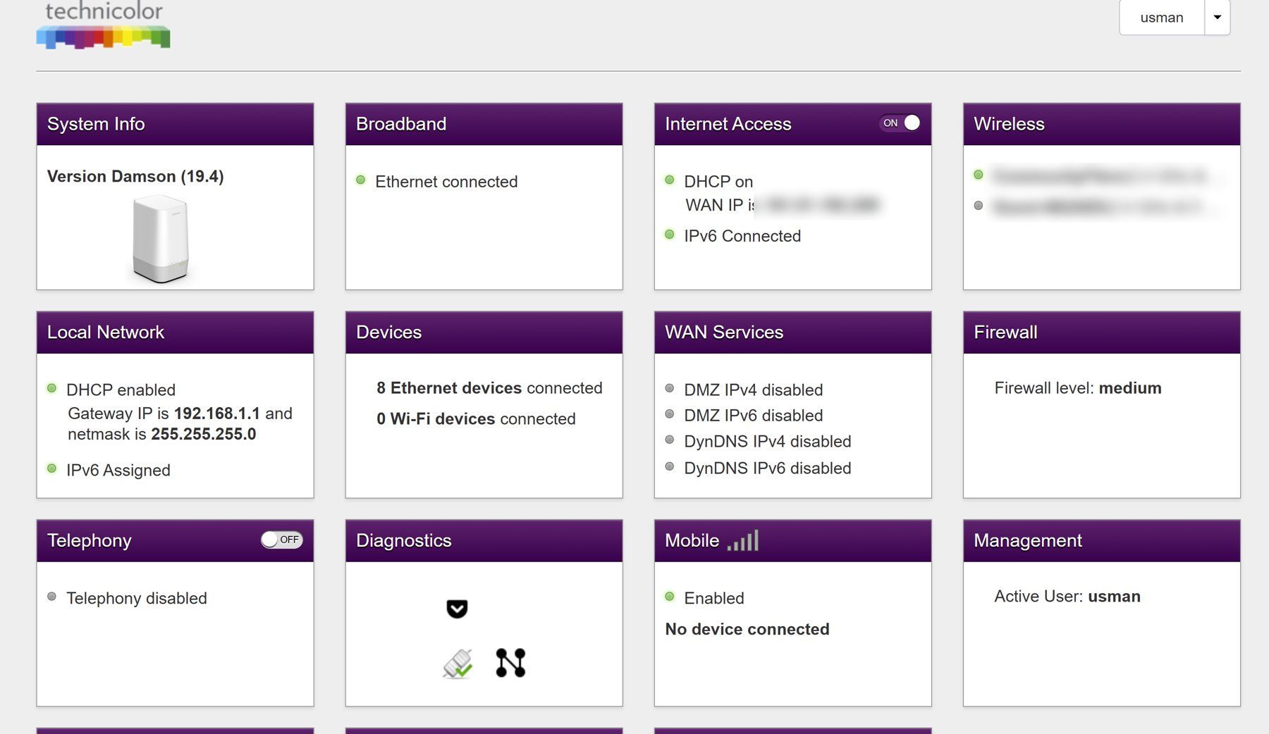
Nothing exotic. The cluster lives on my normal home network: one flat 192.168.1.0/24 subnet, shared with every phone, laptop and TV in the house, behind the ISP-supplied router (a Technicolor FGA5330CFL). The router does DHCP and DNS for everything.
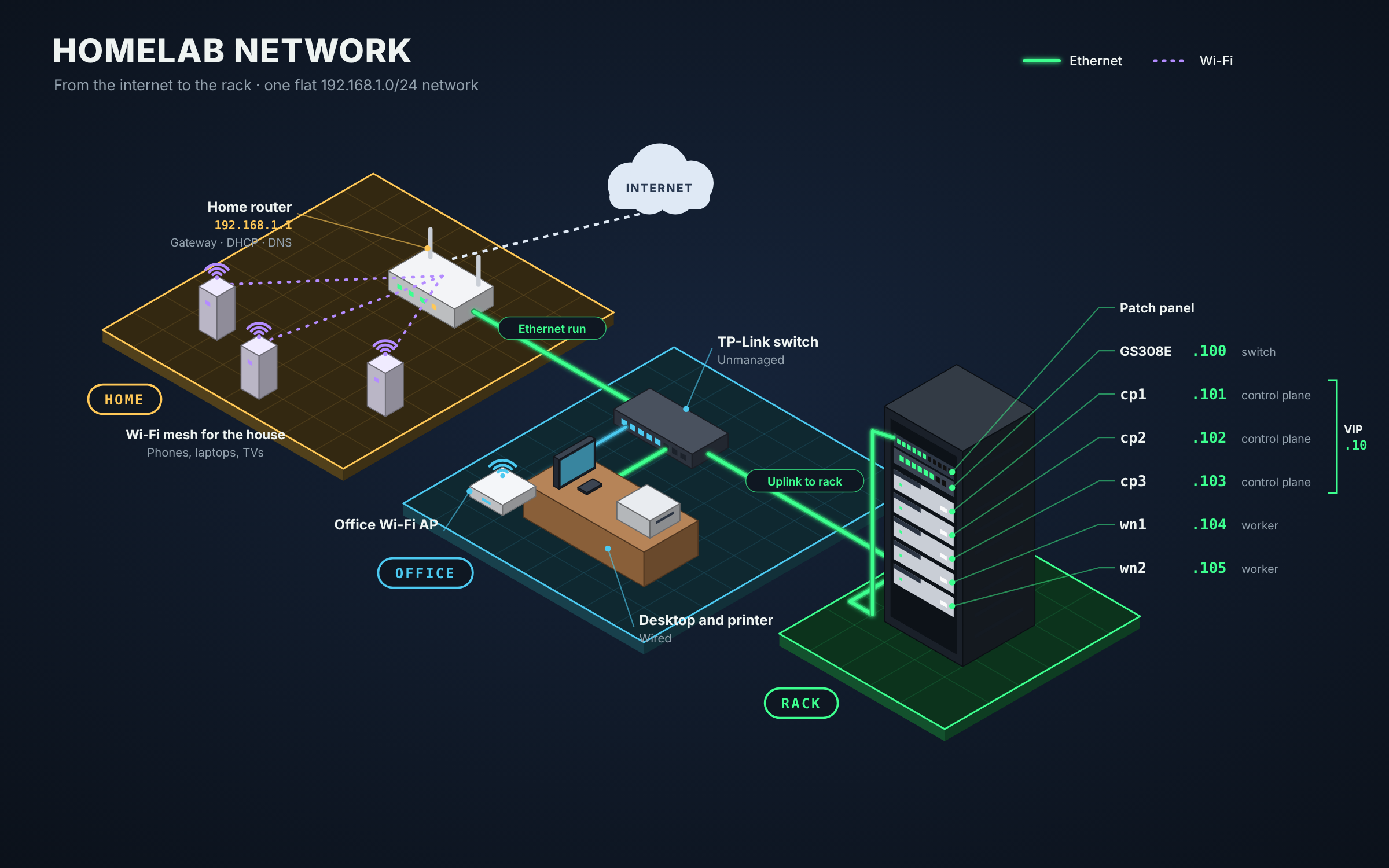
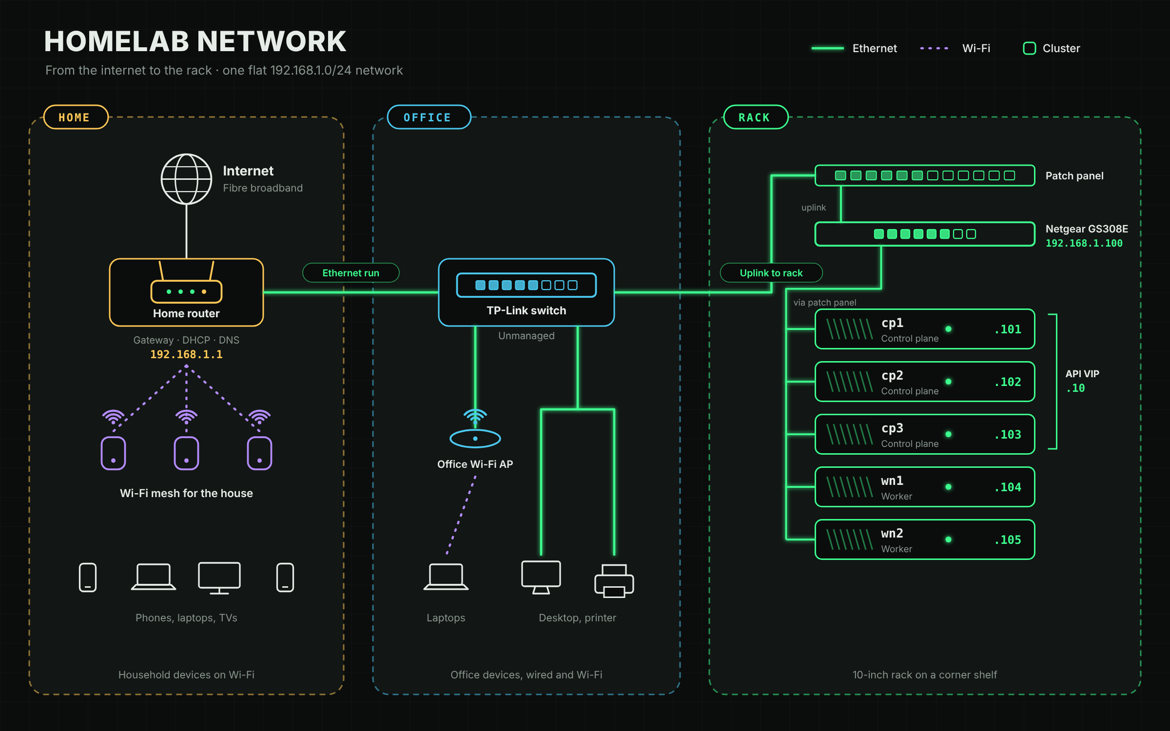
Physically, it’s three hops from the router to the cluster:
- Home: the router connects to the internet and provides Wi-Fi to the rest of the house through a mesh system.
- Office: a single Ethernet run goes from the router to a TP-Link unmanaged switch in my office. That switch feeds the wired office devices and a separate Wi-Fi access point for the office.
- Rack: one more cable goes from the TP-Link switch into the rack’s patch panel and on to the Netgear switch, which connects the five nodes through the same patch panel.
No VLANs, no separate lab network, no fancy firewall. That’s a deliberate starting point, not the end state. A flat network is the simplest thing that works, and I wanted the cluster running before adding layers. Separating the lab from the household is on the list for later.
The address plan
Here’s the whole plan in one table:
| Address | What lives there | How it’s assigned |
|---|---|---|
.1 |
Router (gateway and DNS) | Router itself |
.2–.9 |
Reserved for Kubernetes LoadBalancer services | Static, outside DHCP |
.10 |
Kubernetes API (floating virtual IP) | Static, outside DHCP |
.11–.15 |
Intel AMT remote management, one per node | Static, outside DHCP |
.16–.19 |
Spare | Not yet used |
.20–.254 |
DHCP pool for everything else in the house | DHCP |
.100 |
Netgear GS308E switch | DHCP reservation |
.101–.105 |
The five cluster nodes | DHCP reservations |
There are two kinds of address here, and the split matters.
Addresses that must never come from DHCP live below .20: the Kubernetes API’s floating address, the AMT management addresses and the range set aside for load balancers. These are claimed by the cluster or the hardware itself, not handed out by the router. If any of them were inside the DHCP pool, sooner or later the router would give one to somebody’s phone, and two devices would fight over the same address.
Addresses that come from DHCP, but always the same one are the switch and the nodes. They ask the router for an address like any other device, but the router has a reservation for each MAC address, so they always get the same IP.
Making room: moving the DHCP pool
Out of the box, the router’s DHCP pool ran from .2 to .254, which is almost the whole subnet. That left nowhere safe for static addresses.
So the first change was moving the start of the pool to .20. That carved out .2–.19 for the static addresses, with some headroom. I may widen that gap later if I need more static addresses, but it’s enough for now.
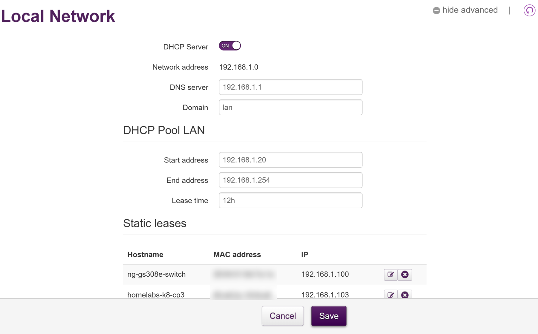
Before moving the pool, I checked that nothing was already using an address below .20. Shrinking the pool doesn’t kick existing devices off their addresses straight away, but it does mean the router stops managing them. Better to know first.
Reservations for the nodes
The switch and the five nodes each have a DHCP reservation, tied to their MAC address.
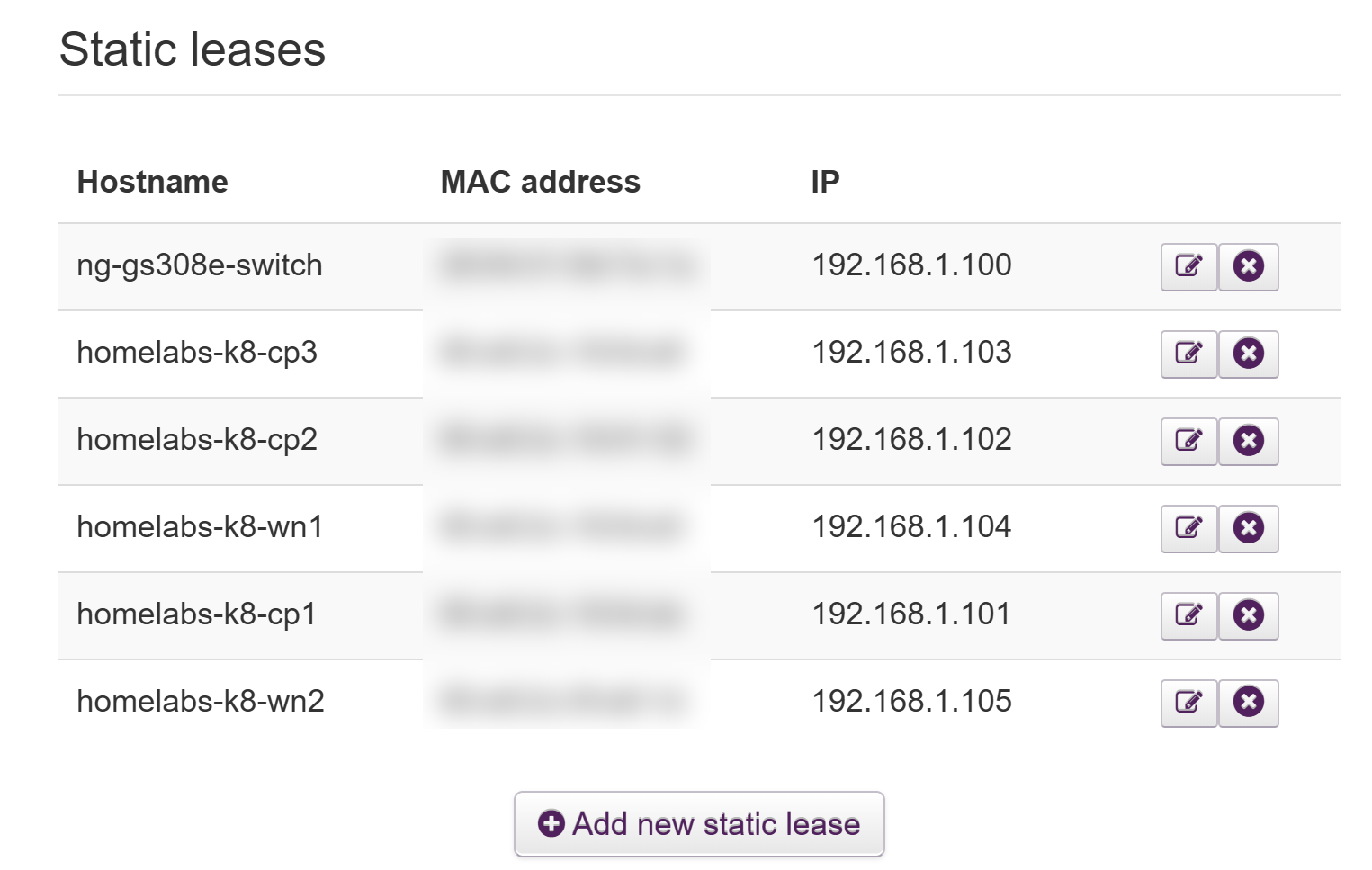
The numbering is deliberately boring:
.100is the switch. I gave it a reservation so I can always find its management page..101,.102,.103are CP1, CP2 and CP3..104,.105are WN1 and WN2.
The last digit matches the node number, so I never have to look anything up. Starting at .101 also leaves a clean run of addresses for more nodes later.
Why reservations rather than static IPs set on each node? Three reasons:
- One source of truth. Every address on the network lives in one place, the router, right next to every other device in the house. There’s no second list to keep in sync.
- Simpler node configs. Each Talos node just asks for an address, so there’s no per-node network section to get wrong. Reinstalling a node needs no network changes at all.
- The router knows they’re taken. With a reservation, the router will never hand that address to anything else. A static IP set only on the node is invisible to the router.
The trade-off is that the nodes depend on the router remembering those reservations. If the router were ever reset to factory settings, the nodes would come back on random addresses and the control plane wouldn’t find itself. That’s one reason these screenshots exist: they double as my backup of the router’s config. Setting static addresses in the Talos configs themselves, kept in Git, is the more “infrastructure as code” approach, and I may move to it once the cluster’s config is managed that way.
The floating API address
Kubernetes clients — kubectl, the worker nodes, anything else that talks to the cluster — need one address for the Kubernetes API. If that address belonged to a single control-plane node, losing that node would take the whole API with it, even with the other two healthy.
Talos solves this with a virtual IP. The three control planes share 192.168.1.10. At any moment one of them holds it, chosen through etcd. If that node goes down, another takes over the address, and clients carry on talking to .10 without noticing.
Two things follow from that:
- It has to sit outside the DHCP pool. The router doesn’t know it exists, so it would happily give it to something else.
- It depends on etcd. If the cluster loses quorum, nobody can win the election and the address disappears. That’s correct behaviour, but it surprised me the first time I saw it.
I got to watch the failover happen sooner than planned. That’s a story for a later post.
Two addresses per node
Every EliteDesk actually has two IP addresses on the same network cable: one for the operating system, from the reservations above, and one for Intel AMT, the remote-management controller built into the hardware. AMT addresses are set by hand in each machine’s firmware, so they live in the static range at .11–.15.
AMT is what lets me power-cycle a node and see its screen from my laptop. It gets its own post next.
Saving space for load balancers
On a cloud provider, creating a Kubernetes service of type LoadBalancer gets you an external IP automatically. On bare metal, nothing provides one, so the service sits at Pending forever.
The usual fix is MetalLB, which hands out addresses from a pool you give it. I haven’t installed it yet, but I’ve already set aside .2–.9 for it. Eight addresses sounds small, but most apps will sit behind a single ingress address, so it should be plenty.
The switch
The switch is a Netgear GS308E: eight gigabit ports, with a basic web interface for things like VLANs and port monitoring. For now I haven’t changed a single setting on it. Its only configuration is the DHCP reservation on .100, so I can reach its management page when I need it.
Five ports go to the nodes through the patch panel, one goes to the router, and two are spare. Gigabit is plenty for this cluster today. (Getting every node to actually run at gigabit was another matter. That’s in the remote management post.)
Check before you claim
The one habit I’d recommend from all this: before you reserve or claim an address, prove nothing else is using it.
Before setting the reservations for the switch and nodes, I went through the router’s device list to make sure none of .100–.105 was already in use. I did the same before moving the pool start to .20, checking nothing was sitting below it.
The API address needed less checking by design. .10 sits outside the DHCP pool, so the router will never hand it out, and nothing else on the network is configured to use it. Planning it that way up front means there’s nothing to conflict with when the first control plane claims it. (I’ll show how I confirmed that in the Talos install post.)
What I’d change next
The plan works, but it’s a first version:
- Separate the lab from the household. A VLAN for the cluster would keep its traffic, and its experiments, away from everyone else’s devices. The GS308E supports VLANs, so this is mostly a configuration job.
- Local DNS. Right now I use IP addresses everywhere. Running local DNS (something like Pi-hole) would let me use names instead.
- A bigger static range. If I end up with more static addresses than expected, moving the pool start to around
.30gives plenty of room without disturbing anything.
None of this needs to happen before the cluster is useful. That was the point of planning first: the addresses are settled, and everything else can be layered on top without re-addressing a running control plane.
Next up: how I look after five nodes on a corner shelf without ever plugging in a monitor.